Friction Welding :Why Inertia Drive Is Superior
01
What Is Friction Welding
Friction welding is a solid-state joining process. Two workpieces rub against each other under axial pressure; friction at the interface converts mechanical energy into heat and brings the metal into a plastic state. Once rotation stops, an upset force is applied and the plasticised metal is expelled as flash, completing the joint. No filler metal is added — the bond is formed by the parts' own metal — so the joint has a forged structure rather than a cast one, with no porosity and no solidification cracking. A joint between like metals can be stronger than the parent metal.
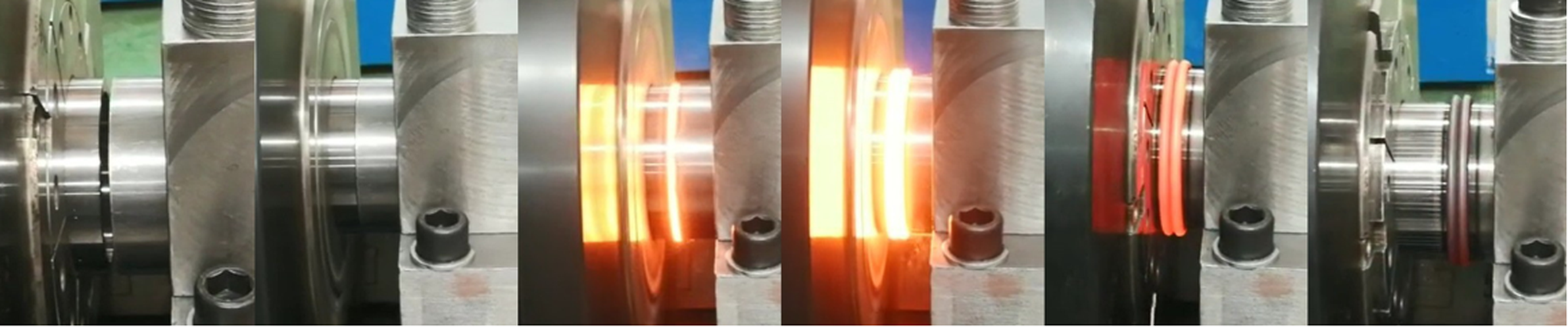
Figure 4. Contact, heat generation, upset, flash, weld complete
02
Two Friction Welding Processes
Classified by how the rotation is driven, friction welding comes in two types, and their process characteristics differ substantially.
2.1 Continuous Drive Friction Welding (CDFW)
The motor holds the workpiece at a constant speed throughout the friction stage. Once the set burn-off is reached, a brake stops the rotation abruptly, and the upset force is then applied to complete the joint.
2.2 Inertia Friction Welding (IFW)
A flywheel is accelerated to a set speed and then disconnected from the motor. The energy stored in the flywheel (½Jω²) is the entire heat input budget. Once contact begins, the flywheel delivers that energy to the interface and the speed decays on its own — no motor holding a constant speed, and no brake stopping it.
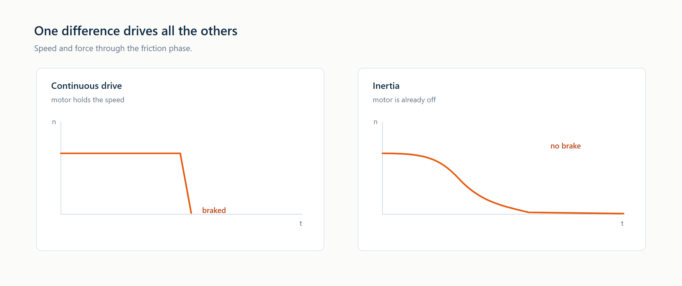
Figure 5. Rotational speed versus time: continuous drive (braked) versus inertia (natural decay)
Table 1. Continuous drive friction welding compared with inertia friction welding
|
Item |
Continuous drive (CDFW) |
Inertia (IFW) |
|
Heat source |
Motor, holds a constant speed |
Flywheel stored energy, speed decays naturally |
|
How rotation stops |
Brake applied at the end |
No brake — speed falls to zero on its own |
|
Weld width |
0.5–2 mm (conventional metals) |
60–110 µm (titanium alloys, superalloys) |
|
Heat-affected zone |
Wider, marked grain growth |
Very narrow, structure close to parent metal |
|
Flash |
Irregular and bulky, tends to leave gaps |
Regular and small |
|
Tensile strength |
85–95% of parent metal (like metals) |
90–100% of parent metal (like metals) |
|
Fatigue life |
60–80% of parent metal |
80–100% of parent metal |
|
High-temperature performance |
Suited to service below 300 °C |
Remains stable above 500 °C |
|
Typical applications |
Exhaust valves, small and medium shafts |
Aero-engine disc-to-shaft joints, superalloy joints |
Note: the figures above are for like-metal joints. Dissimilar-metal joints will be somewhat lower on both counts.
03
Why Inertia Friction Welding Is Superior
One line in the table explains most of the others: CDFW brakes to a stop at the end, while IFW lets the speed decay on its own. That single difference is what produces the advantages below.
3.1 A Narrow Weld and a Small Heat-Affected Zone
The energy is released in a very short time, so the heat stays almost entirely near the interface. The weld is narrow and the heat-affected zone small; the metal on either side of the bond line remains close to its forged structure.
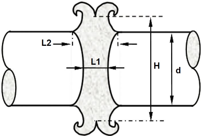
Figure 6. A narrow weld and a small heat-affected zone (L1 weld, L2 HAZ)
3.2 Small Flash, Good Dimensional Retention
The upset travel is set by how much metal has to be expelled. Flash that is small and regular means little axial shortening: the designed compression height is the height obtained. The gallery wall is not damaged by a large volume of flash, less heat is left in the crown, and dimensional retention is excellent.
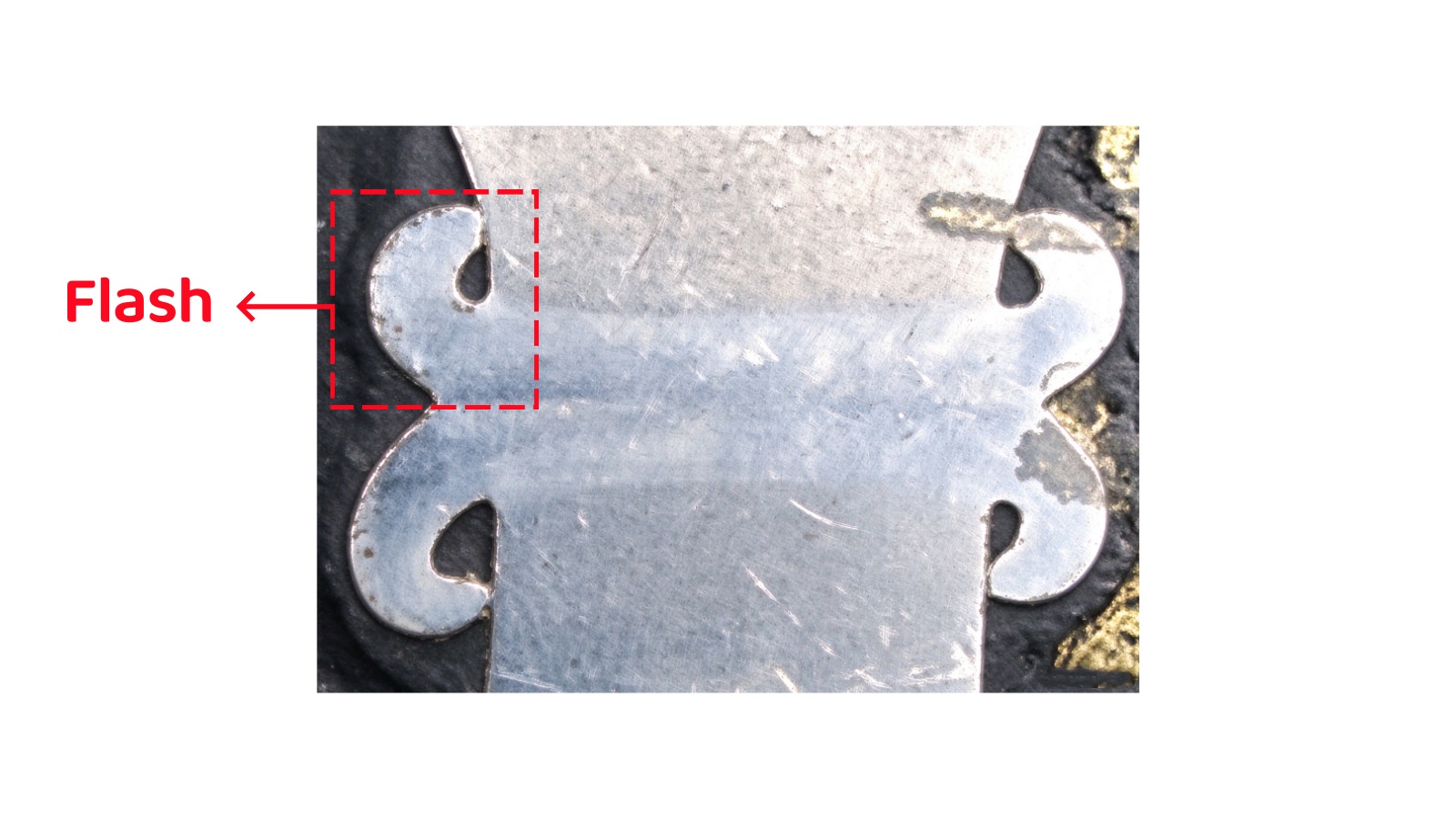
Figure 7. Small flash, good dimensional retention
3.3 An Intact Bond Line, Better Fatigue Performance
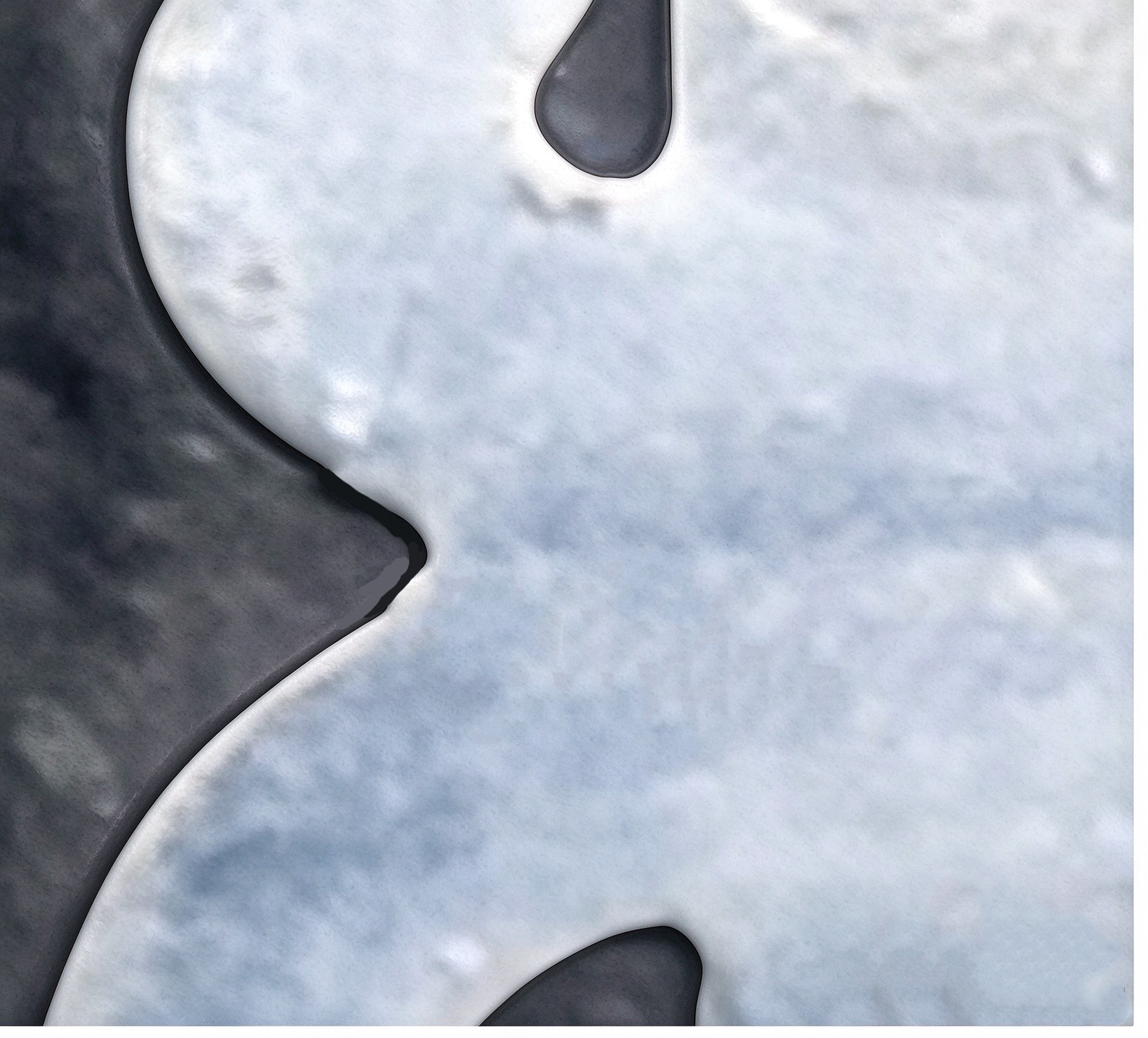
The integrity of the bond line is critical to fatigue life. In CDFW, the spindle is stopped abruptly while the interface remains in a high-temperature plastic state; sudden braking induces shear at the bond line, and the residual microcracks act as fatigue initiation sites (Figure 8). By contrast, IFW only dissipates flywheel energy without braking impact, yielding an intact bond line (Figure 9).
|
Figure 8. Microcracks induced by braking shear in CDFW |
Figure 9. Intact IFW bond line, free of defects |
04
Conclusion
With its narrow weld, intact bond line and stable dimensions, inertia friction welding is superior to continuous drive friction welding in critical metal joining, and is the preferred forming process for precision parts such as the monobloc piston.
The Monobloc Piston: An Inevitable Direction of Technical Evolution